 |
| Inductors Explained |
The basics how inductors work working principle
An inductor, also called a coil, choke, or reactor, is a passive two-terminal electrical component that stores energy in a magnetic field when electric current flows through it.[1] An inductor typically consists of an insulated wire wound into a coil around a core.
When the current flowing through an inductor changes, the time-varying magnetic field induces an electromotive force (e.m.f.) (voltage) in the conductor, described by Faraday's law of induction. According to Lenz's law, the induced voltage has a polarity (direction) which opposes the change in current that created it. As a result, inductors oppose any changes in current through them.
An inductor is characterized by its inductance, which is the ratio of the voltage to the rate of change of current. In the International System of Units (SI), the unit of inductance is the henry (H) named for 19th century American scientist Joseph Henry. In the measurement of magnetic circuits, it is equivalent to weber/ampere.
Inductors have values that typically range from 1 µH (10−6 H) to 20 H. Many inductors have a magnetic core made of iron or ferrite inside the coil, which serves to increase the magnetic field and thus the inductance. Along with capacitors and resistors, inductors are one of the three passive linear circuit elements that make up electronic circuits.
Inductors are widely used in alternating current (AC) electronic equipment, particularly in radio equipment. They are used to block AC while allowing DC to pass; inductors designed for this purpose are called chokes. They are also used in electronic filters to separate signals of different frequencies, and in combination with capacitors to make tuned circuits, used to tune radio and TV receivers.
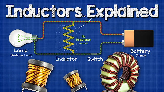
Inductors Explained, in this tutorial we look at how inductors work, where inductors are used, why inductors are used, the different types. We take an in depth look at how the circuits perform with a parallel resistive and inductive load as well as their profile with an oscilloscope.
Related topics:

Post a Comment